Common welding defects and their causes are analyzed as follows:
(1) Can Body Cold Welding
Mechanical Factors:
① Steel plate: incorrect circumference length, non-parallel plate angles, excessive burrs, holes in the steel plate.
② Positioning mold overlap control errors: too high/too low, incorrect horizontal setting, too tight or too loose, guide rail issues.
③ Z-groove: basic setting errors, incorrect head setting, Z-groove wear.
④ Output conveyor: too high or too low, incorrect conveyor speed.
⑤ Conveying errors: issues in the transport between the feeder and lifting guide rails.
⑥ Copper wire forming: worn forming wheels, poor copper wire quality.
Electrical Factors:
① Welding current setting: current set too low.
② Short circuit in secondary welding circuit: insulation issues, foreign objects in excessive Z-groove areas.
③ Welding wheel: worn wire groove causing deviation (see Fig. 3-49(12)).
④ Current stabilizer: regulator malfunction.
(2) Cold Welding at the Can Start
① Steel plate: incorrect plate angles, poor roll forming. Adjust as close to ideal as possible.
② Can feed gearbox: misaligned chain not adjusted, unequal chain spacing, damaged ceramic on chain finger.
③ Lower welding arm: suspension screws not tightened (see Fig. 3-49(6)).
④ Z-groove: contaminants, wear at Z-groove ends, incorrect end height.
⑤ Welding geometry: inaccurate setting, incorrect over-push E value, excessive welding pressure, incorrect push claw setting.
⑥ Mold: worn roller mandrel, positioning roller lacks guiding function, excessive position setting errors.
⑦ Copper wire: tin marks not centered, worn welding wheel groove, copper wire moves too fast, copper wire wheel not rotating smoothly.
⑧ Welding speed: can spacing too large.
(3) Severe Metal Extrusion (Hot Welding)
Mechanical Defects:
① Welding geometry errors during welding: can edges not parallel, improper welding wheel position, worn welding wheel groove.
② Steel plate: burrs during shearing, large thickness variation.
③ Positioning mold: set too low.
④ Can damage during conveying: issues in transport between lifting guide rails and transfer rails.
Electrical Defects:
Welding current: excessive welding current, welding speed v less than its v limit, current controller malfunction.
(4) Formation of Weld Burrs (see Fig. 3-49(9))
Mechanical Defects:
① Steel plate: cutting issues, burrs in material, thickness variation, inconsistent quality within the same batch, contaminants on steel plate, coating in weld area.
② Sizing mold: height setting, relative position to welding level SE (overlap errors), scratches.
③ Welding wheel geometry: optimal wheel position, worn wheel groove, non-parallel wheel axis.
④ Welding pressure: too low.。
Electrical Defects:
Welding current: set too high, current control malfunction.
(5) Incomplete Weld Seam
Mechanical Defects:
① Steel plate cutting: incorrect shear angle, incorrect plate circumference.
② Sizing mold: too low or too high.
③ Synchronization: incorrect synchronization angle.
Electrical Defects:
① Machine settings and detectors: current reduction activated, welding monitor: key set at specified position, stepping function activated.
② Misalignment (see Fig. 3-49(12)).
(6) No Overlap at Can Start
① Steel plate cutting: incorrect shear angle, incorrect circumference.
② Sizing mold: input roller too high, horizontal setting incorrect, sizing mold too loose.
③ Welding geometry: Z-groove height, optimal welding wheel position, upper welding wheel ahead of lower wheel, non-parallel welding wheel axis.
④ Synchronization: excessive synchronization angle, vs too low.
(7) No Overlap at Can End
① Steel plate cutting: incorrect angle, incorrect circumference.
② Sizing mold: horizontal setting, sizing roller not pressed tightly.
③ Welding geometry incorrect.
④ Output conveyor: too high or too low, conveyor speed too fast or too slow.
(8) Excessive Overlap
① Steel plate: incorrect cutting, plate circumference too large, excessive thickness variation.
② Sizing mold: too tight, too high.
③ Z-groove: worn, excessive overlap U (Z-groove error).
(9) Insufficient Overlap (along the entire weld seam)
① Steel plate cutting: plate circumference too short.
② Sizing mold: too loose, too low, poor roller adjustment.
③ Welding wheel geometry: wheel not correctly adjusted to optimal position.
④ Welding pressure: too high, must not exceed 60 daN.
⑤ Roll forming station: plate opened too wide after forming.
(10) Formation of Irregular Weld Spots (see Fig. 3-49(14))
Mechanical Defects:
① Steel plate: too dirty or dusty, scratches in welding area, burrs in material.
② Synchronization: vs < vs\_, welding wheel drive chain too loose.
Electrical Defects:
① Welding current: SCR failure.
② Welding wheel: damaged.
③ Copper wire clutch: slipping.
(11) Severe Roll Forming Defects at Can End (see Fig. 3-49(11))
① Steel plate cutting: edges not parallel.
② Dropper: poor roll forming adjustment, roller clearance, one side of the plate forming defective, load spring for roller force improperly adjusted, other roller positions (plate edges) incorrect.
③ Welding pressure: too high.
④ Synchronization vs too high: can spacing too large.
(12) Formation of Spiral Shape (see Fig. 3-49(14))
① Steel plate cutting: incorrect angle.
② Synchronization: feeding pusher misaligned, additional outfeed conveyor incorrectly set.
③ Sizing mold: too tight, not aligned with conveyor centerline, upper positioning roller misadjusted, ceramic roller not pressed.
④ Infeed gearbox: chain finger misaligned, chain guide head worn unevenly, chain poorly adjusted.
(13) Breakdown Caused by Overheating (see Fig. 3-49(5))
Steel plate: surface contamination.
(14) Welding Defect Illustrations (see Fig. 3-49)
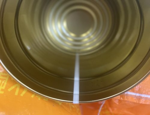
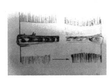
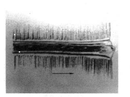
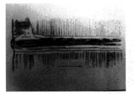
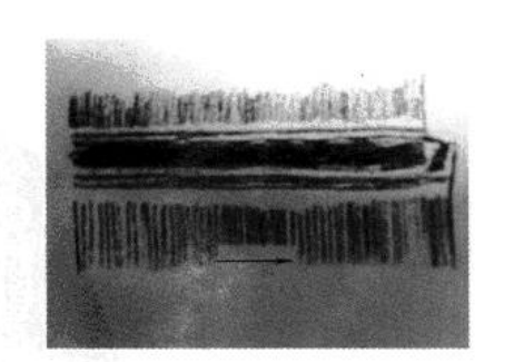
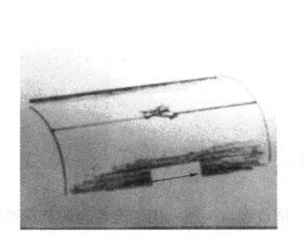
Most of the illustrations were obtained under a microscope in the laboratory. The weld sample images shown are largely influenced by steel plate quality, thickness, coating, welding speed, and machine adjustments. The arrows in the illustrations indicate the welding wheel feed direction during the welding process.
(1)Inner and Outer Views of a Single Welded Can
(2)Severe Extrusion at the Start of the Weld Seam (Outer Side)
(3)Overheating at the End of the Weld Seam (Outer Side)
(4) Misalignment at the Start of the Weld Seam (Outer Side)
(5) Coating Breakdown in the Welded Area Due to Overheating (Outer Side of the Can)
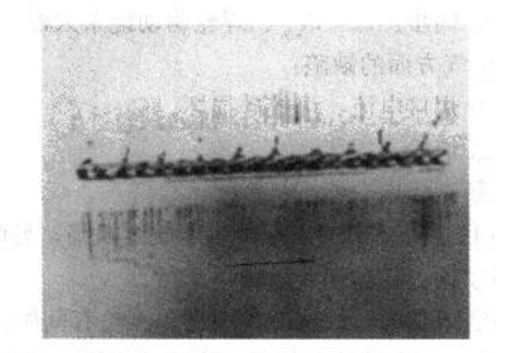
(6) The illustrated phenomenon (outer side) is very rare. Possible causes include vibrations, insufficient stability of the lower welding arm, substandard quality of the metal sheet or copper wire, and welding pressure, frequency, or current not meeting requirements.
The-current-is-increased-at-both-ends-of-the-weld-seam-outer-side.png)
(7) The current is increased at both ends of the weld seam (outer side)
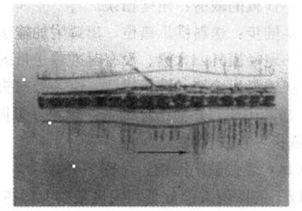
(8) The current is increased at a certain point of the weld seam (outer side)
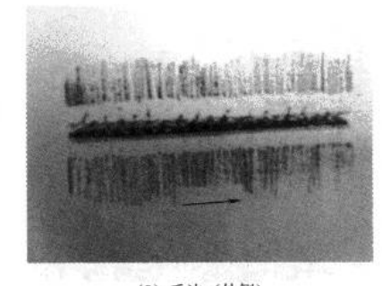
(9) Burrs (outer side)
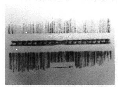
(10) Scratches on the sheet metal along the copper wire (outer side) (first and last sheets).png
.png)
(11) Protrusion of the weld seam after exiting the welding machine (outer side)
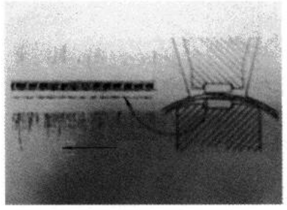
(12) Misalignment on the inner side of the weld seam
Output-conveyor-speed-too-high.png)
(13) Output conveyor speed too high
Irregular-weld-spots.png)
(14) Irregular weld spots