(1) Liquid Coating Weld Seam Coating Process
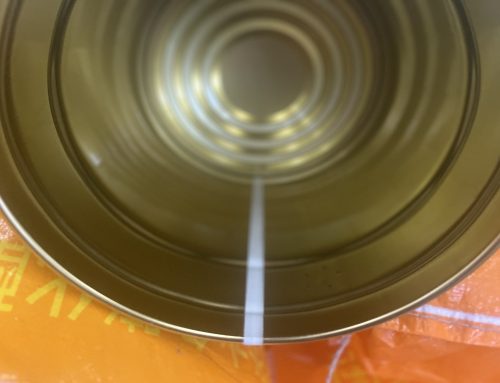
The schematic of the coating layer of liquid coating is shown in Figure 3-54, which can cover the weld seam area. There are multiple process methods to achieve this.
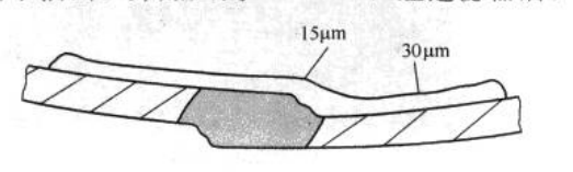
Figure 3-54 Thickness Distribution of Uncured Liquid Coating Layer
① Spray Coating Process: A commonly used method is airless spraying. The principle of airless spraying is as follows: a high-pressure pump draws liquid coating from the coating container and pressurizes it to 2–5 MPa. After passing through a filter, the coating is circulated and heated in the pipeline to 40–65 °C according to process requirements. This increases the solid content of the coating while reducing its viscosity. The coating is then atomized through a specially shaped nozzle and sprayed out in a fan shape. The term “airless” means that no additional air pressure is required to atomize the coating, as shown in Figure 3-55. Overspray between cans is removed by a suction device. The viscosity of the coating should be determined according to the supplier’s specifications or experimental results, typically measured with a No. 4 viscosity cup (100 mL volume, 4 mm orifice) for 15–30 s.
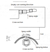
Figure 3-55 Diagram of Liquid Spray Coating
Figure 3-56, Figure 3-57, and Figure 3-58 illustrate the airless spray coating process.
Figure 3-59 shows that even with the same liquid flow rate, the width and thickness of the coating coating vary.
As seen in Figure 3-60, different nozzle types and spray angles affect the coating profile. Adjusting parameters such as viscosity, coating temperature, and pressure in the supply line also changes the width and thickness of the liquid coating.
Another spraying method is air-assisted spray. Its principle is to use air pressure to push the liquid coating from the supply tank to the nozzle, then another air stream atomizes the coating at the nozzle tip, hence the name “air-assisted spray.” This method has lower adaptability to coatings and often results in poor coating quality and overspray; it is now rarely used in the can-making industry.
② Roll Coating for Weld Seam Coating: Roll coating can be performed internally or externally. The method applies liquid coating to the weld seam using a roller. In both cases, liquid coating is delivered from a tank to a coating box under air pressure. A roller immersed in the coating rotates via a motor, transferring the liquid to its surface.
When the welded can moves along the conveyor to the coating roller, the roller applies the coating evenly over the weld seam, forming a uniform coating layer. The coating amount on the roller is controlled by a doctor blade (eccentric block) to adjust the coating thickness. The roller speed matches the can travel speed.
The roller system is mounted in a coating box equipped with a liquid level detection device. For internal coating, the box is mounted on a coating arm connected to the welding arm. Coating viscosity is determined based on the desired effect, typically 30–70 s (4# Ford cup, 100 mL, 4 mm orifice).。
Figure 3-61 shows a schematic of the internal spray coating box, and Figure 3-62 illustrates the internal roll coating process.
The external coating box is mounted on a support frame. Liquid level control is very simple, based on the principle of air pressure balance inside and outside the coating bottle.
The advantages of roll coating include cost-effectiveness, material savings, cleanliness, and suitability for small can diameters and thin tinplate. It works well with medium- to low-speed welding machines, and most coatings from well-known manufacturers are compatible with this method.
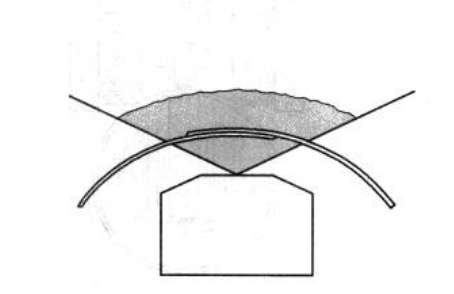
Figure 3-56 Airless spray schematic
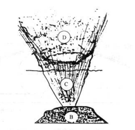
Figure 3-57 Spray coating schematic
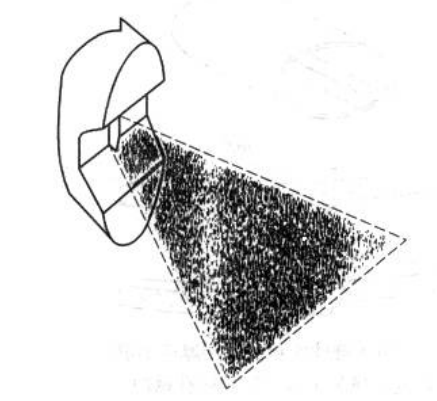
Figure 3-58 Airless spray nozzle atomization schematic
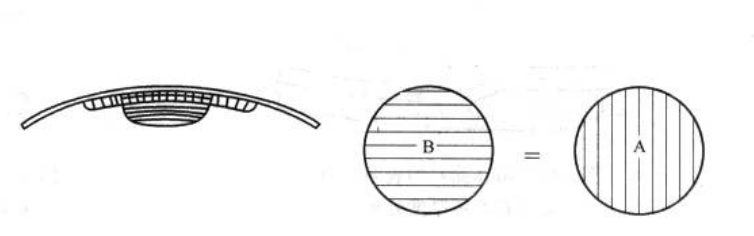
Picture 3-59 Thickness schematic
(2). Parameters Affecting the Coating Coating Effect
① Thickness of the tinplate and the lap height are factors that determine the coating thickness and help avoid micropores in the coating (see Figure 3-63).
② Viscosity of the coating also affects coating thickness and the occurrence of micropores. Higher viscosity results in a thicker coating with better protection, but makes application more difficult, prone to air bubbles, harder to cure, and requires longer baking/curing equipment. Lower viscosity produces a thinner coating with poorer protection, and after curing, the weld area is prone to delamination and micropore corrosion, though fewer air bubbles form during curing (see Figure 3-64).
③ Coating properties and surface tension effects also determine coating effectiveness. Surface tension causes the coating to be repelled from weld edges and sharp points, leading to thinner coating on weld peaks. Surface tension is a physical phenomenon that cannot be eliminated, only controlled, and is largely influenced by changes in coating viscosity during baking/curing. Adding certain additives can improve this effect (see Figure 3-65).
④ Solvents, coatings, and foaming behavior also affect the coating effect. The frequency of micropores largely depends on the mixing ratio of solvent and coating.
⑤ Adhesion of the coating coating. Poor adhesion can affect subsequent operations, such as flanging and sealing, making the coating layer prone to damage.
⑥ Cooling of the weld after can body welding also affects the liquid coating layer. Excessive heat in the weld area can damage the liquid coating layer.
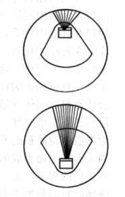
Figure 3-60 Effect of Nozzle on Coating Performance
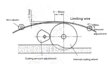
Figure 3-61 Internal Diagram of the Roll Coating Recoat Box
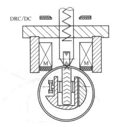
Figure 3-62 Internal Roll Coating Process Diagram
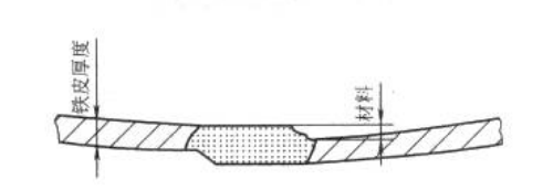
Figure 3-63 Effect of Sheet Metal Thickness on Coating Performance
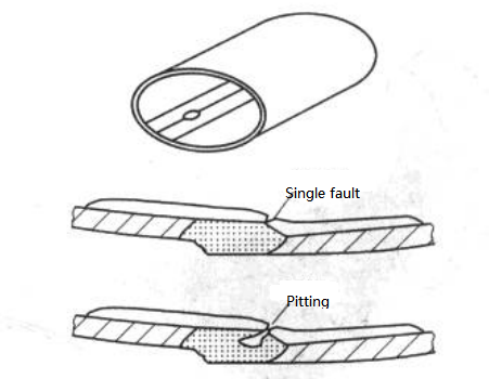
Figure 3-64 Insufficient liquid coating thickness can lead to breaks and pinhole corrosion in the weld area
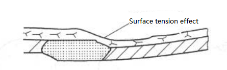
Figure 3-65 Surface tension of liquid coating affecting the thickness distribution of the coating strip
Flow can cause the middle area of the weld to thin, affecting the coating coating quality. High-quality coatings should have the following characteristics:
The coating does not chemically react with the filled contents.
After coating and curing, the coating exhibits good mechanical stability, flexibility, hardness, and adhesion.
After curing, the molecular density is high, and the molecules do not undergo chemical changes under certain conditions (e.g., high-temperature sterilization).
The polymerization (curing) temperature is relatively low.
The following parameters also affect the coating process:
Solid content of the liquid coating
Temperature sensitivity of the coating
Mass per unit area of the coating layer
Distribution of the coating layer due to surface tension
Visual appearance after curing
There are many types of liquid coatings commonly used, including:
Organic sol type
Epoxy resin type
Vinyl coatings
Acrylic coatings
Phenolic resin type