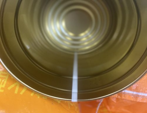
Airless Spraying System: Most manufacturers use this system for internal weld seam liquid touch-up. It is generally based on an improved system originally developed by NORDSON (USA). The main components include a pneumatic paint pump (air-to-liquid pressure ratio 1:16), filter, paint heater, paint hydraulic pressure regulator, spray gun, nozzle, and circulation valve group, forming a closed-loop circuit. An electrical control system regulates the paint heater temperature and the spray nozzle’s on/off timing.
During the touch-up process, liquid paint is atomized through a special nozzle and sprayed onto the weld seam. Adjustments can be made to nozzle size, paint viscosity, paint temperature, spraying pressure, and thinner to achieve optimal coverage. Nozzles can be either air-atomized or airless. The principle of airless spraying is shown in Figure 3-73.
Paint Viscosity: It should be prepared according to the manufacturer’s data or experimental results. Viscosity is typically measured with a DIN4 cup (volume 100 mL, 4 mm orifice, ambient temperature 20℃), calculating the relative viscosity from the time it takes for the paint to flow out.
Advantages: Easy to adjust, good coverage, especially suitable for high-speed welding machines. By selecting different nozzles, most paints can be accommodated.
Disadvantages: With certain paints, the nozzle orifice can easily clog, so a good filter is essential.
Spraying Process: Shown in Figure 3-74; the overspray extraction system is shown in Figure 3-75.
After the paint pump draws paint into the pipeline (Figure 3-76), the pressure can be increased to 2–4 MPa.
Main Components of the Spraying System:
① Liquid Paint Booster Pump: Driven by air, the piston cylinder moves up and down, increasing liquid paint pressure at a 16:1 ratio to the required level, usually 2–4 MPa. The required pressure depends on the chosen nozzle, paint viscosity, paint temperature, and the width of the touch-up area.
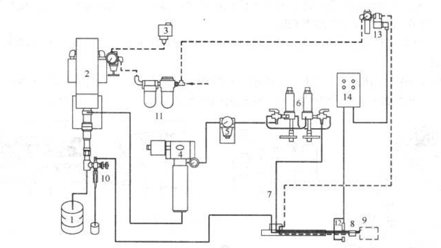
Figure 3-73 NORDSON airless spray pipeline schematic
1. Paint bucket 2. Paint pump 3. Pressure switch 4. Heater 5. Voltage regulator 6. Filter 7. Paint hose 8. Spray gun
9. Nozzle 10. Backflow switch 11. Oil-water separator 12. Sensor 13. Solenoid valve 14. Timer
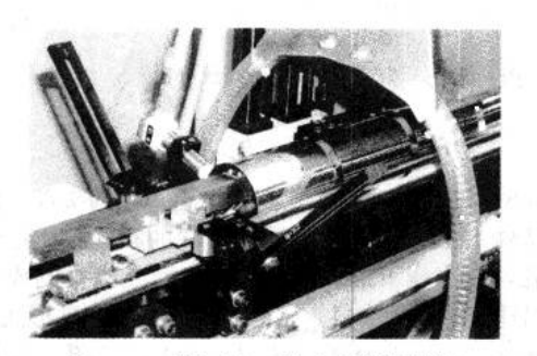
Figure 3-74 Spraying process, device for extracting overspray
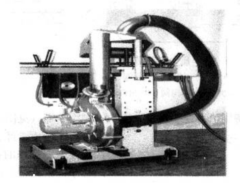
Figure 3-75 Overspray exhaust system at the spraying site
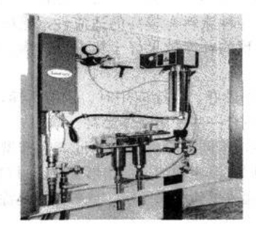
Figure 3-76 Spray paint piping system
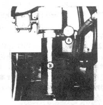
Figure 3-77 Spray paint heater
A-Thermometer B-Heating
② Paint Heater (see Figure 3-77): Reduces the viscosity of the diluted liquid paint. After spraying, it increases the solid content, accelerates solvent evaporation, reduces surface tension, and improves the adhesion of the paint layer. Therefore, the liquid paint pipeline system usually forms a closed loop with a circulation valve group, ensuring that the paint continuously flows through the heater. This keeps the paint at a consistent temperature and viscosity throughout the pipeline.
③ Paint Pressure Regulator (see Figure 3-78): Since the paint pump operates on a piston stroke principle, the pressure fluctuates. This valve is used to stabilize the liquid paint pressure.
④ Spray Gun (see Figures 3-79 and 3-80): The spray gun has an internal cylinder connected to the paint valve. Controlled by air pressure and a spring, it can quickly open to allow paint to flow rapidly to the nozzle for spraying, and it can also close quickly to stop the flow.
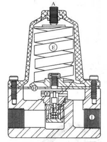
Figure 3-78 Paint pressure regulator
A – inlet, E – spring, F – piston,
H – pressure plate, G – check valve, I – outlet
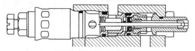
Figure 3-79A9A spray gun for low-speed welding machine
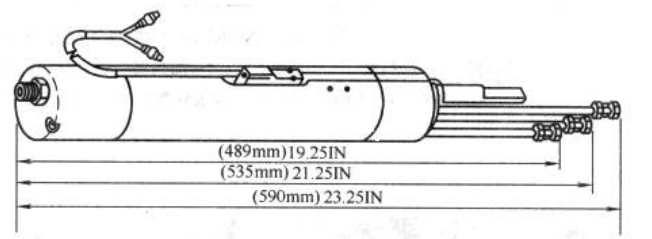
Figure 3-80A16A spray gun for high-speed welding machine
It is worth mentioning that the airless spray nozzle (see Figure 3-81) is installed on the spray gun when it is working. Its head is made of carbide material, and the special shaped small hole is made by special processing. The liquid paint passes through the special hole of the nozzle and forms a fan-shaped atomization under high pressure. This nozzle is made into a variety of styles and different hole diameters to adapt to different paints. Its small hole shape has three forms:
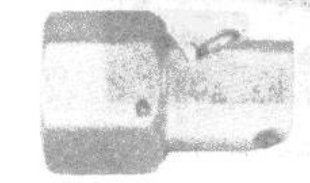
Figure 3-81 Special nozzle for airless spraying
① Standard Type (S-standard): This nozzle has a “cat-eye” shaped small hole. The spray forms a misty fan shape, but may have some overspray, making it suitable only for certain liquid paints.
② Cross-Cut Type (X-cross-cuts): This nozzle has a square-shaped hole. The spray forms a clear misty fan with good adaptability to various paints, producing a more even coating. For some paints, this nozzle achieves better touch-up results than the standard type, while for certain special paints, the effect is similar.
③ Flow Coating Type (F-FLOW-COATING): This nozzle provides the best touch-up results, with minimal overspray, good coverage, and compatibility with high-viscosity paints. It is suitable for both conventional and some specialized liquid paints.
Nozzles wear over time, and the effect differs depending on nozzle type and paint used. For standard nozzles, wear increases flow rate and narrows the fan shape. For cross-cut nozzles, wear increases flow rate but widens the fan shape, which can self-correct.
When selecting a nozzle, choose according to the specific liquid paint through testing or as recommended by the paint supplier. Additionally, when switching paints in the system, clean the pipelines and follow paint instructions carefully, using the proper thinner to avoid adverse chemical reactions or poor results.